Différences entre versions de « Projets:Vesc tool setup »
| (30 versions intermédiaires par 3 utilisateurs non affichées) | |||
| Ligne 1 : | Ligne 1 : | ||
| + | {{Infobox projet | ||
| + | |Image principale=FW 02 wiring.jpg | ||
| + | |Description=This project presents in details how to configure a VESC board (Vedder Electronic Speed Control) | ||
| + | |Porteur de projet=GuillaumeMHK | ||
| + | |Contributeurs=André, Gael, Nicop35, SulianeMHK | ||
| + | |Fabmanager=Yo | ||
| + | |Référent documentation=Delphine | ||
| + | |Catégorie de handicap=Mobilité | ||
| + | |Mobilité=Motorisation fauteuil | ||
| + | |Etat d'avancement=Abandonnés | ||
| + | |Statut de la documentation=Complète | ||
| + | |Relecture de la documentation=Non vérifiée | ||
| + | |Techniques=électronique | ||
| + | |Durée de fabrication=de 2 à 4 h | ||
| + | |Coût matériel=De 50 à 100 euros | ||
| + | |Niveau=Moyen | ||
| + | |Licence=by-sa | ||
| + | |Projet date=2019-09-06 | ||
| + | |Nom humanlab=Humanlab_MHK | ||
| + | }} | ||
| + | |||
| + | |||
== Project overview == | == Project overview == | ||
| − | This project presents in details how to configure a | + | This project presents in details how to configure a VESC board ('''V'''edder '''E'''lectronic '''S'''peed '''C'''ontrol) : |
| − | * Make the wiring and the required electrical connections to use this electronic | + | * Make the wiring and the required electrical connections to use this electronic board in order to control an electrical bike engine (as well as other types of engines such as DC, brushless) |
| − | * Configure an electronic | + | * Configure an electronic VESC board with a dedicated program (VESC Tool) in order to control an electrical bike engine with an electrical scooter type accelerator throttle. |
==Special thanks== | ==Special thanks== | ||
| Ligne 13 : | Ligne 35 : | ||
| − | '''Merci/Thanks/Danke | + | '''Merci/Thanks/Danke Schön Benjamin Vedder :)''' |
==Warning== | ==Warning== | ||
| Ligne 99 : | Ligne 121 : | ||
| − | ''' | + | '''cost-efficient alternative to the VESC card''' NOT TESTED |
| − | * | + | * There are other engine controlling electronic boards that are 10 times cheaper but these cannot be reprogrammed. This means you cannot select the speed at which the vehicle goes nor adjust the acceleration curve, you can find these here: |
[https://www.banggood.com/fr/DC-12V-36V-15A-500W-Brushless-Motor-Controller-Hall-BLDC-Driver-Board-p-1311440.html?rmmds=myorder&cur_warehouse=CN ESC low cost banggood] | [https://www.banggood.com/fr/DC-12V-36V-15A-500W-Brushless-Motor-Controller-Hall-BLDC-Driver-Board-p-1311440.html?rmmds=myorder&cur_warehouse=CN ESC low cost banggood] | ||
| Ligne 107 : | Ligne 129 : | ||
| − | ''' | + | '''Optional''' |
| − | * | + | * Stabilized powering to test if you don't have a battery |
| − | * | + | * Additional cabling for extension cables if needed |
| − | * | + | * Cable gland to seal the cable feedthrough |
| − | === | + | ===Pictures of the components=== |
<gallery mode="slideshow"> | <gallery mode="slideshow"> | ||
| − | File:Clone-carte-VESC-preparee.JPG| | + | File:Clone-carte-VESC-preparee.JPG|VESC board |
| − | File:Carte-version-VESC-.JPG| | + | File:Carte-version-VESC-.JPG|Or read the version of the board |
| − | File:Batterie-ref.JPG| | + | File:Batterie-ref.JPG|Bike battery reference |
| − | File:Carte vesc potentiometre.JPG| | + | File:Carte vesc potentiometre.JPG|VESC board with potentiometer (to control acceleration) |
| − | File:ARU.JPG| | + | File:ARU.JPG| Emergency killswitch |
| − | File:Cable capteur.JPG| | + | File:Cable capteur.JPG| Sensor wires |
| − | File:Cable moteur.JPG| | + | File:Cable moteur.JPG| Engine cable |
| − | File:Cable longueur voulue.JPG| | + | File:Cable longueur voulue.JPG| Cable cut at wished length |
| − | File:Poignee.JPG| | + | File:Poignee.JPG| Acceleration handle |
| − | File:Connecteurs.JPG| | + | File:Connecteurs.JPG| Connectors to link the handle to the board |
</gallery> | </gallery> | ||
| − | == | + | == Required tools == |
| − | * | + | * Soldering iron (Powerful enough to work with heavy gauge cables) |
| − | * | + | * Tin |
| − | * | + | * Heat shrink sleeve |
| − | * | + | * Crimping tool |
| − | == | + | == Cost == |
| − | * | + | * VESC board + Hall effect sensor cable = 92 $ |
| − | * | + | * Battery + Charger + brushless motor = 0€ thanks to "La petite Rennes" |
| − | * | + | * Clamp bracket : 15€ x 2 = 30 € |
| − | * | + | * Acceleration handle = 8 € |
| − | == | + | == Fabrication time == |
| − | ''' | + | '''Fabrication time is given on an indicative basis and may vary, ref : [https://en.wikipedia.org/wiki/Murphy%27s_law Murphy's Law]''' |
| − | * | + | * Metallic chassis fabrication : 1 to 2 days (working hours) |
| − | * | + | * First installation of the completed device (Chassis + electronic component) on the chair : 2 to 3 hours |
| − | * | + | * Wiring set up : 1 to 2 hours |
| − | * | + | * Programming process of the board : 1 to 2 hours |
| − | * Installation | + | * Installation of the completed device on the chair with practice : 5 to 10 minutes |
| − | == | + | == Source files == |
| − | + | You will find our Configuration Settings in the provided ZIP file as of July 4th, 2019: | |
| − | + | XML file : Motor configuration | |
| − | + | XML file : App configuration | |
[[File:4-7-19.zip]] | [[File:4-7-19.zip]] | ||
| − | == | + | ==Electronic component : VESC board preparation== |
| − | === | + | ===Overview schematics=== |
[[File:FW 02 wiring.jpg|left|1200px]] | [[File:FW 02 wiring.jpg|left|1200px]] | ||
| Ligne 171 : | Ligne 193 : | ||
<br clear=all> | <br clear=all> | ||
| − | ===<u>--> | + | ===<u>--> WARNING - (This step is now obsolete since we've chosen a new board provider)<--</u> - Wiring if use of a naked VESC board=== |
| − | + | Strip and tin the power supply wires and then cut back so that the stripped wires are not too long. | |
[[File:BALa0ZVr o.jpg|350px]] [[File:QI4Jvynz o.jpg|350px]] | [[File:BALa0ZVr o.jpg|350px]] [[File:QI4Jvynz o.jpg|350px]] | ||
| Ligne 181 : | Ligne 203 : | ||
| − | + | Wrap the capacitor's lugs (holding parts) and then solder them (''WARNING'' You have to solder the capacitor according to its polarity. The + (longest lug) on the red wire and the - (shortest lug) on the black. Then check the continuity of the wire with a multimeter and the insulation of one wire in relation to the other. | |
[[File:YLaFF5AM o.jpg|350px]] [[File:BNy8yi8P o.jpg|350px]] | [[File:YLaFF5AM o.jpg|350px]] [[File:BNy8yi8P o.jpg|350px]] | ||
| Ligne 187 : | Ligne 209 : | ||
<br clear=all> | <br clear=all> | ||
| − | + | Solder the power supply wires to the board by first putting tin on the + and - terminals and then placing the wires directly on them. | |
| − | |||
[[File:P2jZXvcJ o.jpg|300px]] [[File:Wr20V0Ep o.jpg|300px]] [[File:Z319LbTM o.jpg|300px]] | [[File:P2jZXvcJ o.jpg|300px]] [[File:Wr20V0Ep o.jpg|300px]] [[File:Z319LbTM o.jpg|300px]] | ||
| Ligne 194 : | Ligne 215 : | ||
<br clear=all> | <br clear=all> | ||
| − | + | Tin the other two extremities of the wires. | |
[[File:QHpaYd3K o.jpg|350px]] [[File:GqRkBPJE o.jpg|350px]] | [[File:QHpaYd3K o.jpg|350px]] [[File:GqRkBPJE o.jpg|350px]] | ||
| Ligne 200 : | Ligne 221 : | ||
<br clear=all> | <br clear=all> | ||
| − | + | Tin the three ends on the board, then the two ends of the cables that will feed the three electromagnetic coils of the motor (three-phase cables). | |
[[File:Mui7MH74 o.jpg|350px]] [[File:Zgn3aFPt o.jpg|350px]] | [[File:Mui7MH74 o.jpg|350px]] [[File:Zgn3aFPt o.jpg|350px]] | ||
| Ligne 206 : | Ligne 227 : | ||
<br clear=all> | <br clear=all> | ||
| − | + | Solder them flat on the three previously tinned ends of the board. | |
| − | |||
[[File:MtdZoe8O o.jpg|left|350px]] | [[File:MtdZoe8O o.jpg|left|350px]] | ||
| Ligne 213 : | Ligne 233 : | ||
<br clear=all> | <br clear=all> | ||
| − | ===<u>--> | + | ===<u>-->End of the obsolete step<--</u>=== |
| − | === | + | ===Fabrication of the necessary wiring=== |
| − | * | + | * Wiring connections from the motor to the board |
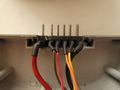
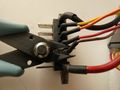
[[File:connections_cables_moteur_carte.JPG|700px]] | [[File:connections_cables_moteur_carte.JPG|700px]] | ||
| − | * | + | * Link the battery to the VESC board and implementation of a killswitch (emergency stop button) |
<gallery mode="slideshow"> | <gallery mode="slideshow"> | ||
| − | File:1 batterie + support.jpg| | + | File:1 batterie + support.jpg| The battery and its support |
| − | File:2 prise alimentation.jpg| | + | File:2 prise alimentation.jpg| The power plug |
| − | File:3 demonter support.jpg| | + | File:3 demonter support.jpg| Disassemble the battery support to extract the original ESC |
| − | File:4 sortir la prise de son logement.jpg| | + | File:4 sortir la prise de son logement.jpg| Extract the plug |
| − | File:5 couper fils inutile.jpg| | + | File:5 couper fils inutile.jpg| Cut the useless wires |
| − | File:6 demonter boitier.jpg| | + | File:6 demonter boitier.jpg| Disassemble the ESC to maximize the length of the recuperated wires |
| − | File:7 couper fils le plus long possible.jpg| | + | File:7 couper fils le plus long possible.jpg| Inside of the ESC |
| − | File:8 resultat.jpg| | + | File:8 resultat.jpg| The result |
| − | File:9 preparer alimentation.jpg| | + | File:9 preparer alimentation.jpg| Preparation of the VESC power supply |
| − | File:10 couper fils alimentation.jpg| | + | File:10 couper fils alimentation.jpg| Cut the VESC power supply wires |
| − | File:11 fil moins dans ARU.jpg| | + | File:11 fil moins dans ARU.jpg| Plug in the - wire in the killswitch (Emergency Stop Button) |
| − | File:12 souder fil plus.jpg| | + | File:12 souder fil plus.jpg| Solder the + wire and protect it with the heat shrink sleeve. |
</gallery> | </gallery> | ||
| − | * | + | * Handle with the adapted connector |
<gallery mode="slideshow"> | <gallery mode="slideshow"> | ||
| − | File:Poignée accélérateur.jpg| | + | File:Poignée accélérateur.jpg| Acceleration handle |
| − | File:Connecteur d'origine de la poignée.jpg| | + | File:Connecteur d'origine de la poignée.jpg| Original connectors of the handle |
| − | File:Couper et dénuder les fils.jpg| | + | File:Couper et dénuder les fils.jpg| Cut and strip the wires |
| − | File:Connecteur jst au pas de 2mm.jpg| | + | File:Connecteur jst au pas de 2mm.jpg| JST Connector with 2mm step |
| − | File:Sertir les cosses sur les fils.jpg| | + | File:Sertir les cosses sur les fils.jpg| Crimp the connectors on the wires |
| − | File:Mettre les cosses dans le connecteur.jpg| | + | File:Mettre les cosses dans le connecteur.jpg| Put the connectors in |
| − | File:Verso de la carte avec identification des bornes.jpg| | + | File:Verso de la carte avec identification des bornes.jpg| Terminal identification on the board |
| − | File:Connecter a la carte.jpg| | + | File:Connecter a la carte.jpg| Connect to the board while respecting the colors : Red = +3.3V, Black = GND and Green = ADC |
</gallery> | </gallery> | ||
| − | * | + | * Wiring for the Hall effect sensors |
<gallery mode="slideshow"> | <gallery mode="slideshow"> | ||
| − | File:1 le câble des capteurs.jpg| | + | File:1 le câble des capteurs.jpg| The sensors' wire |
| − | File:2 câble moteur.jpg| | + | File:2 câble moteur.jpg| Original motor wire |
| − | File:3 câble moteur coupé à la bonne longueur.jpg| | + | File:3 câble moteur coupé à la bonne longueur.jpg| Motor wire cut at the right length |
| − | File:4 correspondance câble moteur et câble capteurs.jpg| | + | File:4 correspondance câble moteur et câble capteurs.jpg| Matching between motor wire and sensor wire |
| − | File:5 Couper câble moteur.jpg| | + | File:5 Couper câble moteur.jpg| Cut sensor wire |
| − | File:6 relier câble moteur et câble capteurs.jpg| | + | File:6 relier câble moteur et câble capteurs.jpg| Link motor wire and sensor wire |
| − | File:7 Brancher le cable des capteurs sur la carte.jpg| | + | File:7 Brancher le cable des capteurs sur la carte.jpg| Plug the sensors' wire to the board |
</gallery> | </gallery> | ||
| − | === | + | ===Placing the card in its dedicated housing=== |
| − | ( | + | (Pictures soon) |
| − | === | + | ===Programming the electronic board=== |
| − | ==== | + | ====Preliminary step==== |
/////////////////////////////////////////////////////////////////////////////////////////////////////////////////////////////////////////////////////////////////////////////////////////////////////////////////////////////////////////////////////////////////////////////// | /////////////////////////////////////////////////////////////////////////////////////////////////////////////////////////////////////////////////////////////////////////////////////////////////////////////////////////////////////////////////////////////////////////////// | ||
| − | <u>''' | + | <u>'''To enter the software in the board you will need to connect the board via usb AND power it from the bike battery (or a laboratory power supply) thanks to the 2 black and red wires.'''</u> |
/////////////////////////////////////////////////////////////////////////////////////////////////////////////////////////////////////////////////////////////////////////////////////////////////////////////////////////////////////////////////////////////////////////////// | /////////////////////////////////////////////////////////////////////////////////////////////////////////////////////////////////////////////////////////////////////////////////////////////////////////////////////////////////////////////////////////////////////////////// | ||
| Ligne 283 : | Ligne 303 : | ||
| − | + | The Electronic Speed Controler) is used to manage the operation of the engine. | |
| − | == | + | ==Step by step software configuration== |
| − | + | You will first need to download the software, you will need to purchase it ... for 0€ But you can also support the project by purchasing the software [https://vesc-project.com/node/17/ VESC Tool] | |
| − | + | Open the VESC Tool software. | |
| − | + | A picture is worth a thousand explanations! | |
| − | + | You will be able to edit the tabs by following the mouse cursor on the images. | |
| − | + | You might get a message the first time you open the software on udev rules. Click Yes to install them. | |
| Ligne 306 : | Ligne 326 : | ||
| − | === VESC Tool> | + | === VESC Tool>Connection tab === |
| − | + | In Connections tab>USB Serial, click on Refresh serial port list (Baud Option on 115200) | |
| Ligne 313 : | Ligne 333 : | ||
| − | + | If no port is detected, leave the USB cable plugged in, and restart the software. | |
| − | + | Then click the Connection icon. | |
| Ligne 321 : | Ligne 341 : | ||
| − | + | If you get the following error message, you will need to update the firmware (see next step) | |
| Ligne 327 : | Ligne 347 : | ||
| − | === VESC Tool> | + | === VESC Tool>Firmware tab>Included File === |
| − | + | Click on the Firmware tab | |
| Ligne 334 : | Ligne 354 : | ||
| − | + | See the original documentation in English if needed. [https://vesc-project.com/node/179 Documentation] | |
| − | + | WARNING: the wrong firmware can permanently damage the board if it is not the right firmware! | |
| − | + | Select the board version in the left window (V 4.12) and VESC_default.bin in the right window. | |
| − | + | Upload the VESC firmware VESC_default.bin corresponding to hardware v4.12. | |
| Ligne 345 : | Ligne 365 : | ||
| − | + | Information message: the card configuration will be overwritten by the new firmware. | |
| Ligne 351 : | Ligne 371 : | ||
| − | + | Once the new firmware is uploaded, please wait the required 10 seconds and then disconnect the power from the board. | |
| Ligne 357 : | Ligne 377 : | ||
| − | Message | + | Message informing that the Firmware is uploaded. Wait for at least 10 seconds, then disconnect the USB and then reconnect. |
| Ligne 363 : | Ligne 383 : | ||
| − | + | Reconnect the board | |
| Ligne 370 : | Ligne 390 : | ||
=== VESC Tool>Motor settings>General === | === VESC Tool>Motor settings>General === | ||
| − | + | We will now configure the board for our engine by selecting Motor settings>General from the left menu. | |
| Ligne 383 : | Ligne 403 : | ||
=== VESC Tool>Motor settings>General>Voltage === | === VESC Tool>Motor settings>General>Voltage === | ||
| − | + | In the "Battery Cutoff Calculator" window at the bottom of the main window, enter 12 cells if you are using Arcade bike batteries. Otherwise refer to the documentation of the batteries you are using. Click Apply to confirm. | |
| Ligne 394 : | Ligne 414 : | ||
=== VESC Tool>Motor settings>General>RPM === | === VESC Tool>Motor settings>General>RPM === | ||
| − | + | Indicate the maximum value of motor rotation in the MAX ERPM parameter (12000RPM here) (revolutions per minute). | |
| − | + | If you want to limit the speed of your device this is where it is controlled, feel free to test it. | |
| − | - (M.Ar) - | + | - (M.Ar) - If you want to facilitate reversing (free wheel to allow reversing) you have to indicate this value in the max ERPM reverse box : -0,10 |
| Ligne 404 : | Ligne 424 : | ||
=== VESC Tool>Motor settings>Wattage === | === VESC Tool>Motor settings>Wattage === | ||
| − | + | Indicate the power of your engine in the Maximum Wattage box: 250W here | |
| − | - (M.Ar) : | + | - (M.Ar) : you need to indicate this value in the Maximum Breaking Wattage box : -0,1W |
| Ligne 412 : | Ligne 432 : | ||
=== VESC Tool>Motor settings>Temperature === | === VESC Tool>Motor settings>Temperature === | ||
| − | + | There is nothing to change on the Temperature tab. | |
[[File:17_MS_General_Temperature.png|1200px]] | [[File:17_MS_General_Temperature.png|1200px]] | ||
| − | |||
=== VESC Tool>Motor settings>Advanced === | === VESC Tool>Motor settings>Advanced === | ||
| − | + | There is nothing to change in the Advanced tab. | |
| Ligne 427 : | Ligne 446 : | ||
=== VESC Tool>Motor settings>BLDC>General=== | === VESC Tool>Motor settings>BLDC>General=== | ||
| − | + | On the left menu go to: Motor settings > BLDC then on the central window select the General tab. | |
| − | + | Copy the parameters of the following picture. In the Sensormode setting choose "Sensored". | |
| Ligne 434 : | Ligne 453 : | ||
| − | + | In the bottom window on the "detect BLDC parameters" tab : | |
| Ligne 440 : | Ligne 459 : | ||
| − | + | Click on the icon of the triangle in a circle (play icon) ''(WARNING: this will start the engine)''. | |
| − | + | Make sure that the motor is not under load (that nothing brakes it or prevents it from functioning). | |
| − | + | If you use the MHK power bench, the belt must not be tensioned at all.''' | |
| Ligne 451 : | Ligne 470 : | ||
| − | + | You get the hall sensor table of your motor (you can record and archive these parameters) : | |
| Ligne 457 : | Ligne 476 : | ||
| − | + | Follow-up of the obtained result: | |
| Ligne 463 : | Ligne 482 : | ||
=== VESC Tool>Motor settings>BLDC>sensorless=== | === VESC Tool>Motor settings>BLDC>sensorless=== | ||
| − | + | Sensorless tab : it is not useful since we do not use the Hall sensors of the motor | |
=== VESC Tool>Motor settings>BLDC>Sensors=== | === VESC Tool>Motor settings>BLDC>Sensors=== | ||
| − | + | Sensors tab: Click on Apply, and the table automatically fills itself with the right values | |
| Ligne 474 : | Ligne 493 : | ||
[[File:26 MS BLDC sensors apply.png|1200px]] | [[File:26 MS BLDC sensors apply.png|1200px]] | ||
| − | === | + | ===Save the motor configuration=== |
| − | ''' | + | '''This step is used to memorize your configuration in the VESC board''. |
| − | + | In the right-hand menu, click on the button : Write motor configuration | |
| Ligne 489 : | Ligne 508 : | ||
| − | + | For the setting "App to use" : Select "ADC" | |
| Ligne 495 : | Ligne 514 : | ||
=== VESC Tool>App settings>ADC>General=== | === VESC Tool>App settings>ADC>General=== | ||
| − | - | + | - General Tab : Select Duty Cycle |
| − | + | OR | |
| − | - (M.Ar) - | + | - (M.Ar) - Select Duty Cycle Reverse Center (which allows to reverse without the wheel preventing it) |
| Ligne 506 : | Ligne 525 : | ||
=== VESC Tool>App settings>ADC>Mapping=== | === VESC Tool>App settings>ADC>Mapping=== | ||
| − | + | Mapping Tab : You will need to configure your gas handle (acceleration handle) | |
| Ligne 512 : | Ligne 531 : | ||
| − | + | In the right column activate the RT and RT APP icons (you will consequently see the values in real time). | |
| Ligne 518 : | Ligne 537 : | ||
| − | + | In the bottom window: ADC Voltage Mapping : | |
| − | + | select "Duty Cycle" or "Duty Cycle Reverse Center ((M.Ar) if you chose to have this option by implementing the switch that allows to toggle from one mode to the other (normal mode and freewheel mode) | |
| Ligne 525 : | Ligne 544 : | ||
| − | + | If you chose Duty Cycle Reverse Center : | |
| − | - | + | - Press the min and max reset button |
| Ligne 532 : | Ligne 551 : | ||
| − | + | Set the selection button (switch) to M Ar to reach the minimum (that is 0V) : Photo 41 | |
| Ligne 538 : | Ligne 557 : | ||
| − | + | Then set the button (switch) to normal mode and turn the accelerator to the minimum and maximum to reach the threshold values: | |
| − | + | Click on "Apply" | |
| − | + | View beforehand | |
| Ligne 548 : | Ligne 567 : | ||
| − | + | Afterwards view | |
| Ligne 554 : | Ligne 573 : | ||
| − | + | In the right menu, save with the Write App Configuration button | |
[[File:45 Write App Config.png|1200px]] | [[File:45 Write App Config.png|1200px]] | ||
| − | |||
===FINALISATION Motor Settings>Additional infos=== | ===FINALISATION Motor Settings>Additional infos=== | ||
| − | + | In the left column, go to : Motor settings / Additionnal infos : photo 46 | |
| Ligne 567 : | Ligne 585 : | ||
| − | + | Fill in the fields with the details: change the number of cells, the weight, the brand of the engine, which matches with your configuration. . | |
| Ligne 573 : | Ligne 591 : | ||
| − | + | Add a description to remember your configuration | |
| Ligne 579 : | Ligne 597 : | ||
| − | + | Save by clicking on "Write motor config" in the right menu | |
- Write motor config | - Write motor config | ||
| Ligne 588 : | Ligne 606 : | ||
| − | + | And there you go! Your board is ready to be installed on your vehicle! | |
| − | + | YAY ! :D | |
Version actuelle datée du 20 juillet 2022 à 11:44
| Vesc tool setup
| |
|---|---|
| Informations | |
| Description | This project presents in details how to configure a VESC board (Vedder Electronic Speed Control) |
| Catégorie | Mobilité |
| Sous catégorie mobilité | Motorisation fauteuil |
| Etat d'avancement | Abandonnés |
| Techniques | électronique |
| Durée de fabrication | de 2 à 4 h |
| Coût matériel | De 50 à 100 euros |
| Niveau | Moyen |
| Licence | by-sa |
| Date de création | 2019-09-06 |
| Équipe | |
| Porteur de projet | GuillaumeMHK |
| Contributeurs | André, Gael, Nicop35, SulianeMHK |
| Fabmanager | Yo |
| Référent documentation | Delphine |
| Nom humanlab | Humanlab_MHK |
| Documentation | |
| Statut de la documentation | Complète |
| Relecture de la documentation | Non vérifiée |
Project overview
This project presents in details how to configure a VESC board (Vedder Electronic Speed Control) :
- Make the wiring and the required electrical connections to use this electronic board in order to control an electrical bike engine (as well as other types of engines such as DC, brushless)
- Configure an electronic VESC board with a dedicated program (VESC Tool) in order to control an electrical bike engine with an electrical scooter type accelerator throttle.
Special thanks
The VESC card and the VESC Tool were designed by Benjamin Vedder VESC Project
Merci/Thanks/Danke Schön Benjamin Vedder :)
Warning
- /!\ Do not unplug the engine when the battery is plugged in !
- Reversing is not possible with this type of engine.
When you attempt to reverse with your installed device, the engine opposes a resistance, this is supposed to happen. There is way to facilitate reversing through special settings indicated by the acronym (M.Ar).
Moreover, the implementation of a master switch that cuts the main power (Safety circuit breaker) will hold the engine at rest. You will then be able to reverse.
- In the program, when you have a number with a decimal, you must use a comma (example: -0,10) and not a dot (-0.10).
Useful links
- GesLab project page
- Final documentation of the project
- GitHub upload of the project
- Discussion channel of the project on Framateam
- Realization of the mechanical part (First version) : Mécanique V1 NOTE : This solution is not retained because it is too difficult to set up and remove.
- The second version is similar to the third version. It is however less aesthetic. It is therefore not described here.
- Realization of the mechanical part (Third version) : Mécanique V3
Design brief
For who : For all individuals who wish to enhance their mobility using an electrical bike engine.
For what : For children's bikes, hemiplegic quadricycles, scooters to tow wheelchairs (trotti)
How : By inserting an engine in the wheel using a Dibond flange (Documentation in the works) and by controlling the engine with a dedicated electronic card (VESC).
How much : Thanks to our partnership with La petite Rennes we can provide you with a battery free of charge, a battery charger and an electrical bike engine. In exchange you will be asked to take photos and make videos of your work in order to showcase your project.
You will nonetheless have to purchase components on the internet:
- 1 VESC card: VESC electronic card
- 1 cable for the hall effect sensors : TORQUE ESC Sensor Wires $6.99 (you only need to check the corresponding checkbox after you've bought the card)
- The handle of an electrical scooter : Handle
- 2 Manfrotto clamps to connect the chassis on your chair: Manfrotto clamps
Where : At the Humanlab or at a FabLab near you : FabLab maps by Makery
Existing prototype(s) analysis
There are several existing devices with the same function, here is a non-comprehensive list of these devices:
Models purchasable on the market :
"Do it yourself" model :
Team (Project leaders and contributors)
- Project leader : Guillaume (Trotti), DomiBike, Lila ...
- Contributors : Christian, Delphine, Julien, Super DD
- Referent Fabmanager : Yohann
- Documentation manager : Delphine
Required components
Mandatory
- Prepared VESC card Version 4.12: VESC electronic card
- VESC Tool Free program (v 0.95 is used here): https://www.vesc-project.com/vesc_tool
- 1 acceleration handle. (There are several other control options such as Nunchuck, Potentiometer, wireless etc.)
- 1 electrical bike brushless engine 250 WATTS documentation of the engine in the wheel Motorisation_roue
- 1 bike battery
- Crimp terminals adapted to JST connectors
- mini-USB DATA cable
- 1 female JST connector P:2mm Step:2mm, 6 points
- 1 female JST connector P:2mm Step:2mm, 7 points
- Heavier gauge silicone cable (10AWG, 5mm2) for powering
- Flat or mixed open-end 5/8ths wrench (number 15 spanner) for the securing nuts of the engine on the fork
- Screw, nut 5mm diameter to secure the bike battery support
cost-efficient alternative to the VESC card NOT TESTED
- There are other engine controlling electronic boards that are 10 times cheaper but these cannot be reprogrammed. This means you cannot select the speed at which the vehicle goes nor adjust the acceleration curve, you can find these here:
Optional
- Stabilized powering to test if you don't have a battery
- Additional cabling for extension cables if needed
- Cable gland to seal the cable feedthrough
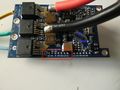
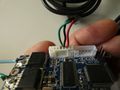
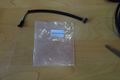
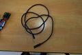
Pictures of the components
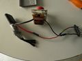
VESC board
Or read the version of the board
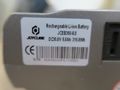
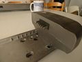
Bike battery reference
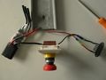
VESC board with potentiometer (to control acceleration)
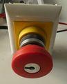
Emergency killswitch
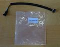
Sensor wires
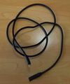
Engine cable
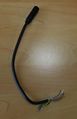
Cable cut at wished length
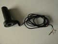
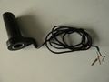
Acceleration handle
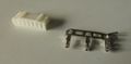
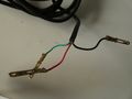
Connectors to link the handle to the board


Required tools
- Soldering iron (Powerful enough to work with heavy gauge cables)
- Tin
- Heat shrink sleeve
- Crimping tool
Cost
- VESC board + Hall effect sensor cable = 92 $
- Battery + Charger + brushless motor = 0€ thanks to "La petite Rennes"
- Clamp bracket : 15€ x 2 = 30 €
- Acceleration handle = 8 €
Fabrication time
Fabrication time is given on an indicative basis and may vary, ref : Murphy's Law
- Metallic chassis fabrication : 1 to 2 days (working hours)
- First installation of the completed device (Chassis + electronic component) on the chair : 2 to 3 hours
- Wiring set up : 1 to 2 hours
- Programming process of the board : 1 to 2 hours
- Installation of the completed device on the chair with practice : 5 to 10 minutes
Source files
You will find our Configuration Settings in the provided ZIP file as of July 4th, 2019:
XML file : Motor configuration
XML file : App configuration
Electronic component : VESC board preparation
Overview schematics

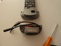
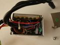
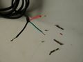
--> WARNING - (This step is now obsolete since we've chosen a new board provider)<-- - Wiring if use of a naked VESC board
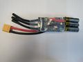
Strip and tin the power supply wires and then cut back so that the stripped wires are not too long.


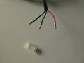
Wrap the capacitor's lugs (holding parts) and then solder them (WARNING You have to solder the capacitor according to its polarity. The + (longest lug) on the red wire and the - (shortest lug) on the black. Then check the continuity of the wire with a multimeter and the insulation of one wire in relation to the other.


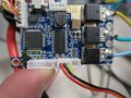
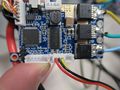
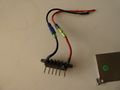
Solder the power supply wires to the board by first putting tin on the + and - terminals and then placing the wires directly on them.


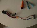
Tin the other two extremities of the wires.


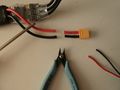
Tin the three ends on the board, then the two ends of the cables that will feed the three electromagnetic coils of the motor (three-phase cables).


Solder them flat on the three previously tinned ends of the board.

-->End of the obsolete step<--
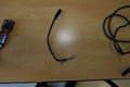
Fabrication of the necessary wiring
- Wiring connections from the motor to the board

- Link the battery to the VESC board and implementation of a killswitch (emergency stop button)
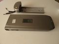
The battery and its support
The power plug
Disassemble the battery support to extract the original ESC
Extract the plug
Cut the useless wires
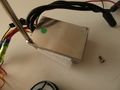
Disassemble the ESC to maximize the length of the recuperated wires
Inside of the ESC
The result
Preparation of the VESC power supply
Cut the VESC power supply wires
Plug in the - wire in the killswitch (Emergency Stop Button)
Solder the + wire and protect it with the heat shrink sleeve.


- Handle with the adapted connector
Acceleration handle
Original connectors of the handle
Cut and strip the wires
JST Connector with 2mm step
Crimp the connectors on the wires
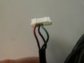
Put the connectors in
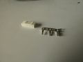
Terminal identification on the board
Connect to the board while respecting the colors : Red = +3.3V, Black = GND and Green = ADC


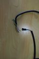
- Wiring for the Hall effect sensors
The sensors' wire
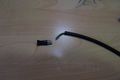
Original motor wire
Motor wire cut at the right length
Matching between motor wire and sensor wire
Cut sensor wire
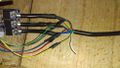
Link motor wire and sensor wire

Plug the sensors' wire to the board


Placing the card in its dedicated housing
(Pictures soon)
Programming the electronic board
Preliminary step
///////////////////////////////////////////////////////////////////////////////////////////////////////////////////////////////////////////////////////////////////////////////////////////////////////////////////////////////////////////////////////////////////////////////
To enter the software in the board you will need to connect the board via usb AND power it from the bike battery (or a laboratory power supply) thanks to the 2 black and red wires.
///////////////////////////////////////////////////////////////////////////////////////////////////////////////////////////////////////////////////////////////////////////////////////////////////////////////////////////////////////////////////////////////////////////////
ESC
The Electronic Speed Controler) is used to manage the operation of the engine.
Step by step software configuration
You will first need to download the software, you will need to purchase it ... for 0€ But you can also support the project by purchasing the software VESC Tool
Open the VESC Tool software.
A picture is worth a thousand explanations! You will be able to edit the tabs by following the mouse cursor on the images.
You might get a message the first time you open the software on udev rules. Click Yes to install them.


VESC Tool>Connection tab
In Connections tab>USB Serial, click on Refresh serial port list (Baud Option on 115200)

If no port is detected, leave the USB cable plugged in, and restart the software.
Then click the Connection icon.

If you get the following error message, you will need to update the firmware (see next step)

VESC Tool>Firmware tab>Included File
Click on the Firmware tab

See the original documentation in English if needed. Documentation
WARNING: the wrong firmware can permanently damage the board if it is not the right firmware! Select the board version in the left window (V 4.12) and VESC_default.bin in the right window.
Upload the VESC firmware VESC_default.bin corresponding to hardware v4.12.

Information message: the card configuration will be overwritten by the new firmware.

Once the new firmware is uploaded, please wait the required 10 seconds and then disconnect the power from the board.

Message informing that the Firmware is uploaded. Wait for at least 10 seconds, then disconnect the USB and then reconnect.

Reconnect the board
VESC Tool>Motor settings>General
We will now configure the board for our engine by selecting Motor settings>General from the left menu.

VESC Tool>Motor settings>General>Current

VESC Tool>Motor settings>General>Voltage
In the "Battery Cutoff Calculator" window at the bottom of the main window, enter 12 cells if you are using Arcade bike batteries. Otherwise refer to the documentation of the batteries you are using. Click Apply to confirm.


VESC Tool>Motor settings>General>RPM
Indicate the maximum value of motor rotation in the MAX ERPM parameter (12000RPM here) (revolutions per minute). If you want to limit the speed of your device this is where it is controlled, feel free to test it.
- (M.Ar) - If you want to facilitate reversing (free wheel to allow reversing) you have to indicate this value in the max ERPM reverse box : -0,10

VESC Tool>Motor settings>Wattage
Indicate the power of your engine in the Maximum Wattage box: 250W here
- (M.Ar) : you need to indicate this value in the Maximum Breaking Wattage box : -0,1W

VESC Tool>Motor settings>Temperature
There is nothing to change on the Temperature tab.

VESC Tool>Motor settings>Advanced
There is nothing to change in the Advanced tab.

VESC Tool>Motor settings>BLDC>General
On the left menu go to: Motor settings > BLDC then on the central window select the General tab. Copy the parameters of the following picture. In the Sensormode setting choose "Sensored".

In the bottom window on the "detect BLDC parameters" tab :

Click on the icon of the triangle in a circle (play icon) (WARNING: this will start the engine).
Make sure that the motor is not under load (that nothing brakes it or prevents it from functioning).
If you use the MHK power bench, the belt must not be tensioned at all.

You get the hall sensor table of your motor (you can record and archive these parameters) :

Follow-up of the obtained result:

VESC Tool>Motor settings>BLDC>sensorless
Sensorless tab : it is not useful since we do not use the Hall sensors of the motor
VESC Tool>Motor settings>BLDC>Sensors
Sensors tab: Click on Apply, and the table automatically fills itself with the right values


Save the motor configuration
'This step is used to memorize your configuration in the VESC board.
In the right-hand menu, click on the button : Write motor configuration

VESC Tool>App settings>BLDC>General

For the setting "App to use" : Select "ADC"

VESC Tool>App settings>ADC>General
- General Tab : Select Duty Cycle
OR
- (M.Ar) - Select Duty Cycle Reverse Center (which allows to reverse without the wheel preventing it)

VESC Tool>App settings>ADC>Mapping
Mapping Tab : You will need to configure your gas handle (acceleration handle)

In the right column activate the RT and RT APP icons (you will consequently see the values in real time).

In the bottom window: ADC Voltage Mapping :
select "Duty Cycle" or "Duty Cycle Reverse Center ((M.Ar) if you chose to have this option by implementing the switch that allows to toggle from one mode to the other (normal mode and freewheel mode)

If you chose Duty Cycle Reverse Center :
- Press the min and max reset button

Set the selection button (switch) to M Ar to reach the minimum (that is 0V) : Photo 41

Then set the button (switch) to normal mode and turn the accelerator to the minimum and maximum to reach the threshold values:
Click on "Apply"
View beforehand

Afterwards view

In the right menu, save with the Write App Configuration button

FINALISATION Motor Settings>Additional infos
In the left column, go to : Motor settings / Additionnal infos : photo 46

Fill in the fields with the details: change the number of cells, the weight, the brand of the engine, which matches with your configuration. .

Add a description to remember your configuration

Save by clicking on "Write motor config" in the right menu
- Write motor config
And there you go! Your board is ready to be installed on your vehicle!
YAY ! :D